MacSD User's Manual
Firmware v2.0.2
1. Overview
Firmware v2.0.2
MacSD is a multi-function SCSI2 target device which uses an SD or MMC card for storage. The circuit board is embedded within a 3D-printed ABS bracket which mounts in a standard 3.5" bay or sled. It is powered through the SCSI connector.
Ports and Controls:
- 50-pin SCSI connector - Used for data transfer and power
- CD audio out - Analog CD audio and MIDI synthesizer output to the logic board or line out jack
- CD audio in - Analog audio pass-through from a CD-ROM drive
- Expansion port
- External LEDs (up to 8)
- MPU-401/TTL 3.3V MIDI input
- MPU-401/TTL 3.3V MIDI output
- Temperature sensors (up to 8)
- Option port
- Activate firmware updates
- Connect hardware CD-ROM eject switches for PCs (up to 3)
- PWM fan connection, fixed or dynamic speed control (up to 2)
- Terminator DIP socket - Accepts a pair of optional resistor arrays for bus termination
- Mini USB port
- Card slot - Accepts SD and MMC cards
- Most SCSI-equipped Macintosh computers
- SCSI Manager
- SCSI Manager 4.3
- Windows 98
- Windows XP
- MS-DOS 6.22 / MSCDEX 2.23
- Adaptec 29xx-series SCSI cards
- Adaptec 15xx-series SCSI cards
- ASPIxDOS.SYS, ASPICD.SYS, ASPIDISK.SYS DOS drivers
- Many SD card slot extenders
- 1.9MB+ per second reads at default 33MHz (PowerMac 6100)
- 3.2MB+ per second reads at 57MHz overclock (PowerMac 6100)
- Up to 7 simultaneous SCSI devices
- Hard drives
- CD-ROM drives
- Composite drives using partition images
- MIDI Synthesizer
- 32KHz stereo, 13.75-bit resolution output through CD audio jack
- Sample-based synthesis
- Accelerates games by replacing QuickTime Musical Instruments
- Up to 32-voice polyphony
- Configurable via INI file and at run time through the terminal interface
- General MIDI compatible
- 128 instruments and sound effects, 13 drum kits
- Three reverb settings
- Adjustable 3D depth effect
- MIDI Interface
- Receives MIDI over SCSI using specialized OMS driver
- Use the internal or external synthesizer without occupying a serial port
- Cooperates with AppleTalk and printing
- Supports OMS 1.2+ and System 7+
- Indirectly supports QuickTime and Apple MIDI Manager via OMS
- Receives and sends MIDI over USB
- Standard USB MIDI device implementation requires no special driver
- Use a Raspberry Pi as an external synthesizer
- Receives and sends MIDI over MPU-401/UART
- Use the internal synthesizer with your PC's SoundBlaster or compatible sound card
- Add a DIN-type MIDI port to your Mac without external interfaces.
- Send MIDI from Macintosh applications and games to external tone generators.
- FAT32 SD card filesystem
- No special software needed to transfer disk images
- Configuration is stored on the card as an INI file
- Firmware updates via SD card
- Floppy/partition image support using composite devices
- Multiple partition images (floppy, Mini vMac, HFS, FAT, ProDOS, etc) are dynamically assembled into a single drive
- Work with multiple floppy images simultaneously, at SCSI speeds
- Add new images without reconfiguration
- Up to 60 partition images across multiple SCSI IDs
- Optional detection and conversion of DiskCopy images to raw
- AppleCD 300i Plus emulation
- Multiple emulated CD-ROM drives
- 8X read throughput
- Supports "cooked" ISO disc images
- Supports BIN/MODE1, redbook/audio and mixed-mode disc images
- Supports TOC and CUE table-of-contents file formats
- 44.1KHz 12.45-bit stereo audio output, concurrent with data transfers
- Full compatibility with AppleCD Audio Player
- Software CD audio volume control
- Eject and load discs from a configured catalog without rebooting
- Boot from CD image
- Hardware eject switch connections for non-Mac platforms
- Multiple termination options
- FPT
- Pull-up
- Pull-down
- MacSD Commander Application
- Easily download files from the SD card to your Mac
- Runs on any System 6 or 7 Mac with 192KB free RAM
- USB Connection
- Standard serial port and MIDI device - No special drivers or applications required
- Set and monitor CD changer, synthesizer and other parameters with a terminal emulator like puTTY.
- Easily send or automate commands to MacSD serial port under Linux with "echo"
- Supply power
2. Card Requirements
Compatible card types are MMC, SDSC (less than 4GB), SDHC (4-32GB) and SDXC (64GB and up). Cards must support 3.3V operation. The card may use either an MBR partition table, or no partition table with the filesystem beginning on block zero. If partitioning is used, partition type must be 0x0B or 0x0C (WIN95 FAT32/LBA). Only the FAT32 filesystem is supported. All files and directories referenced in the configuration file must be located in the root directory of the card. The write protect switch on full size cards will not inhibit writes. A single image file may not exceed 4GB due to FAT32 limitations.
Performance considerations
The speed of random and sequential reads and writes can be improved by using a V60 or better SD card. Faster SCSI hosts will benefit more from a fast card than slower machines.
MacSD's CD audio and synthesizer features require consistently low SD card access times. Some cards may stall up to several hundred milliseconds when accessing specific blocks on the card. This results in breaks in the audio output. A sure sign of slow blocks on a card is CD audio breaking up at the same point in a track. The synthesizer may do the same when specific instruments are played.
Resolving a stalling SD card:
Replacing the card with one of higher quality is recommended. If the same card is to be used, rename the affected synthesizer patch file or CD image on the SD card so that it will not be used, but continues to occupy the same sectors on the card. Then, write a new copy of the file to the SD card.
Filesystem fragmentation
As free space on a FAT32 volume becomes scarce or after files are deleted, files added to it may be written across multiple fragments. Because the FAT32 filesystem does not provide an efficient method of random file access, fragmented image files must be indexed by MacSD before they can be used. When this occurs, the FRAG LED will remain illuminated until power is lost and the SD LED will stay on until indexing is complete. Depending on the size of the image file, indexing can take a significant amount of time, during which the host machine may become temporarily unresponsive or even hang. Fragmentation can be resolved by backing up the contents of the SD card to a computer, reformatting the card and copying the files back to the card. To prevent fragmentation, do not make changes to macsd.ini or other files on the card during the copy process. Because MacSD only writes to image files in place, it cannot contribute to card fragmentation; an unfragmented card installed in the MacSD will remain unfragmented. 3. Configuration
MacSD is configured via a macsd.ini file in the root directory of the SD card. The syntax follows INI file format. Comments may be added to the configuration file beginning with a semicolon. Any text on a line to the right of a semicolon will be ignored. The character set is limited to 7-bit ASCII. Either Windows (\r\n) or Unix (\n) style line termination may be used. The final statement in the configuration file must be terminated with a newline or it will not be parsed.
There are nine section types:
- [general] - General configuration options
- [n:hdd] - Configures a hard drive device, where n is SCSI ID 0-6
- [n:cdrom] - Configures an AppleCD 300i Plus drive, where n is SCSI ID 0-6
- [n:composite] - Configures a composite device, where n is SCSI ID 0-6
- [disc] - Adds a data, audio or mixed mode disc image to the disc catalog
- [midi] - Configures the MIDI routing system
- [synth] - Configures the MIDI synthesizer
- [fan] - Configures a PWM fan output and optional temperature sensor inputs
- [sensor] - Configures a temperature sensor input
Options requiring a Boolean (true/false) parameter will also accept these aliases:
| Boolean aliases | |
| true | false |
| t | f |
| 1 | 0 |
| enabled | disabled |
| yes | no |
| y | n |
MacSD implements a standard serial port over its USB interface. This appears as a COM port in Windows or /dev/ttyACMx in most Linux distributions. Text commands may be sent to MacSD to monitor or modify its parameters. Connecting a WiFi-equipped single board computer such as a Raspberry Pi allows for wireless administration. A connected host may, for example:
- Set the next disc that will be loaded in an emulated CD-ROM drive
- Set the active drum kit, reverb effect, volume, etc on the MIDI synthesizer
- Change the speed of connected fans
- Read temperature sensors
[terminal] configuration section attributes:
- color=[true|false] - Enable color text via VT100 escape sequences. The default value is true.
Serial port settings
The following settings are recommended for the serial terminal interface. Other values may not work correctly:
| USB Serial Port Settings | |||
| Baud rate | 115200 bps | ||
| Data bits | 8 | ||
| Stop bits | 0 | ||
| Parity | None | ||
| Flow control | None | ||
Non-interactive control with a Linux host
When connected to a Linux host, such as a Raspberry Pi, commands may be sent to MacSD using the echo command. This is useful for scripting or automating commands. The device ttyACM0 is used below as an example. The serial device may vary based on your distribution and system configuration.
Example echo usage:
echo "fan speed 90 x" > /dev/ttyACM0
Set synthesizer depth effect to 80:
echo "synth depth 80" > /dev/ttyACM0
PuTTY is a free terminal emulator for Windows, Linux and Mac which can be used with MacSD. Any other VT100-compatible terminal emulator may be used as well.
Setting up PuTTY:
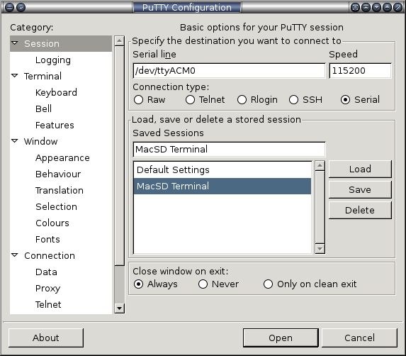
- Select the Serial connection type
- Enter the MacSD serial device for your system
- Set the speed to 115200 bps
- Enter a name for the session
- Click Save
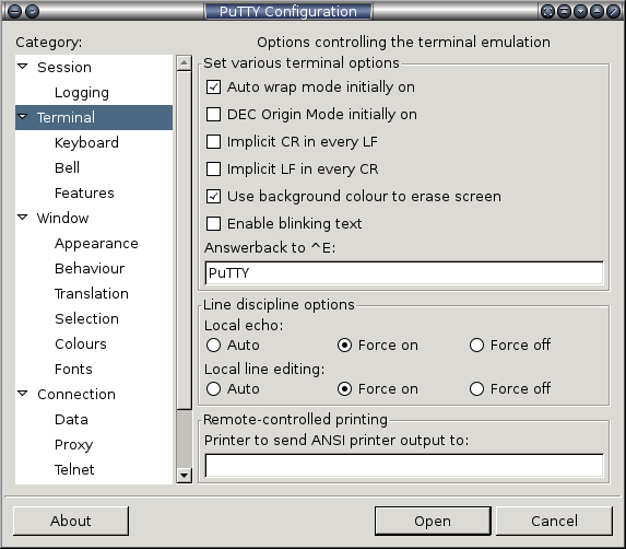
- Select the Terminal category in the left window
- Set the terminal options as shown. The local echo option displays character typed in the PuTTY window. The local line editing option causes PuTTY to wait until enter is pressed before sending any typed characters to MacSD.
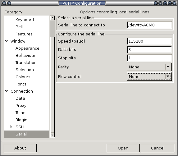
- Select the Serial category in the left window
- Set the serial options as shown.
- Return to the Session category in the left window (shown in the first image) and click Save to preserve the updated options. These settings can now be easily loaded by selecting the saved session and clicking Load.
- Click Open to connect to the terminal.
Sample terminal session:
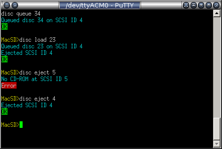
General terminal commands:
- version - Displays version, copyright information and build date of the currently installed firmware.
5. General Configuration Options
[general] configuration section attributes:
- system_clock_mhz=[33|48|57] - This option adjusts the system clock speed. Selecting a value other than the three specified results in a general configuration error condition. The default option is 33MHz. 48MHz and 57MHz are overclocked settings which increase the speed of the MacSD's processor, SCSI data rate and SD card interface. Overclocked settings also increase the CD audio resolution. The internal MIDI synthesizer requires the 57 MHz setting. When overclocking is active, the 'A' LED will illuminate. Some SD cards may not operate reliably at increased clock speeds, especially when SD card extenders are used. Overclocking does not typically yield a significant benefit for 68030 and slower Macs. Before changing this setting, backing up disk images is recommended.
- pcm_tune=[9500-10500] - Adjusts the PCM audio playback rate from 95% to 105% where 100% corresponds to a value of 10000 (default). Values outside of this range result in a general configuration error condition. The value must not contain decimal points or commas. Some games and applications (Descent for example) use system time to determine when to loop an audio track rather than querying the drive for position information. This, combined with clock drift and long tracks can result in playback ending a few seconds early or continuing into the following track before looping. Timing playback in AppleCD Audio Player is useful for finding a compensation value. This option does not affect synthesizer output.
- int_led_intensity=[0-100] - Sets the intensity of the eight internal/on-board status LEDs at the edge of the board. This setting does not affect the intensity of the power, card slot and terminator LEDs. Integers from 0 to 100 are valid. Values outside of this range result in a general configuration error condition. The default value is 50.
- ext_led_intensity=[0-100] - Sets the intensity of external LEDs connected to the expansion port. Integers from 0 to 100 are valid. Values outside of this range result in a general configuration error condition. The default value is 50.
- parity=[true|false] - Generate parity output for all SCSI read transactions. Enabling this option may reduce performance. The default value is false.
| System Clock Speed Options | |||
| 33 MHz Default | 48 MHz Overclock | 57 MHz Overclock | |
| Configuration | system_clock_mhz=33 / none | system_clock_mhz=48 | system_clock_mhz=57 |
| Card frequency | 16.5 MHz | 24 MHz | 28.5 MHz |
| Maximum transfer speed | 1.97 MB/s | 2.86 MB/s | 3.39 MB/s |
| CD audio DAC resolution | 12.45 bit | 13.02 bit | 13.28 bit |
| CD audio gain | -0.53 dB | -0.39 dB | -0.30 dB |
| CD audio dynamic range | 75.0 dB | 78.4 dB | 80.0 dB |
| MIDI synthesizer | Disabled | Disabled | Available |
| MIDI synthesizer resolution | - | - | 13.75 bit |
| MIDI synthesizer dynamic range | - | - | 82.8 dB |
| General Configuration Summary | ||||
| [general] Configuration Section | Terminal Interface | Values | Default | |
| System clock speed | system_clock_mhz = n | 33, 48, 57 | 33 | |
| CD audio rate trim | pcm_tune = n | 9500-10500 | 10000 | |
| Internal LED intensity | int_led_intensity = n | led int n | 0-100 | 50 |
| External LED intensity | ext_led_intensity = n | led ext n | 0-100 | 50 |
| Read parity | parity = n | true, false | false | |
[n:hdd] configuration section attributes:
An HDD device section must define either an image_file or partition:
- image_file=filename - Specifies the image file to use for this drive. The filename is case insensitive and may be enclosed in quotes. No directories are allowed; the file must be located in the root directory of the volume.
- partition=[1-4] - Specifies the primary MBR partition to use for this drive. As an advanced alternative to using an image file, a hard drive device may be mapped directly to a partition. Unlike image files, partitions may exceed 4GB in size. Also, since they occupy a fixed region on the SD card, partitions are not subject to fragmentation. While the main FAT32 partition must have a type of 0x0B or 0x0C, partitions mapped to HDD devices may have any type. Since the MacSD will attempt to use the lowest numbered partition with a type of 0x0B or 0x0C for image files and configuration, using another type for HDD partitions is recommended. The ERR LED will indicate a partition error under these conditions:
- Multiple HDD devices mapped to the same partition
- HDD device mapped to main FAT32 partition
- partition attribute assigned to non-HDD device
- Corrupt, overlapping or missing partition table
- Undefined partition selected
- partition attribute set for HDD device with a defined image_file
7. CD-ROM Device Emulation
MacSD emulates one or more AppleCD 300i 2X CD-ROM drives. Read and seek performance exceed that of the real drive.
[n:cdrom] configuration section attributes:
- image_file=filename - Specifies the image file to use for this CD-ROM drive. The filename is case insensitive and may be enclosed in quotes. No directories are allowed; the file must be located in the root directory of the volume. If this option is not defined, the drive will start empty and an image from the disc catalog will be loaded.
- disc_id_min=[1-100] - The lower bound of the range of disc IDs to load when this drive is ejected. This optional attribute defaults to 1 and must not be greater than disc_id_max.
- disc_id_max=[1-100] - The upper bound of the range of disc IDs to load when this drive is ejected. This optional attribute defaults to 100 and must not be less than disc_id_min.
- disc_id=[1-100] - Specifies the first disc ID that will be mounted from the disc catalog.
- eject_button=[x|y|z] - This optional attribute allows the connection of a physical normally-open pushbutton switch to the X, Y or Z position of the OPTION header, controlling the eject function of a single emulated CD-ROM device. It is intended primarily for non-Macintosh platforms which expect discs to be changed within a game or application that offers no software eject method. Where Windows hosts poll the drive for disc changes and read the new disc as needed, Macintosh hosts disable the drive's eject button and therefore have no reason to expect a disc change. Because of this, using the hardware eject feature with Macintosh computers will likely result in errors.
The eject button can traverse the disc catalog in both directions. After a short button press, a beep is played through the CD audio output to signal the next disc in the catalog is loaded. If the button is held longer until a second, lower-pitch beep is played, the previous disc in the catalog is loaded. Further button presses are ignored until the host polls the drive.
- soft_eject_alert=[true|false] - When set to true, a beep is played through the CD audio output when a software eject event has occurred on the drive. The default value is false.
8. Composite Devices
The composite device feature dynamically combines a series of partition images into a virtual hard drive, complete with an Apple Partition Map. The device entry in the configuration file is bound to a directory on the card using the image_directory option. Images within the specified directory are automatically detected and assembled at boot without additional configuration. HFS, ProDOS, FAT and other filesystems may be used by a Mac equipped with the appropriate extensions. Composite devices are useful for working with floppy/MiniVMac images, transferring files from a PC and more. Multiple SCSI IDs may be configured as composite devices. Partition images are collectively limited to 60. If a fragmented partition image is found, it will be excluded from the disk image and the FRAG LED will illuminate. Booting from composite devices is not currently supported.
[n:composite] configuration section attributes:
- image_directory=directoryname - Specifies a directory at the top level of the card containing one or more partition images.
- convert_images=[true|false] - Partition images encoded in MacBinary, DiskCopy or other format will not normally work with the composite image feature. When the convert_images option is enabled, HFS-formatted images with these encodings can sometimes be converted to the required raw format. This process occurs at startup and is indicated by the FRAG and SD LEDs alterating rapidly. To avoid image corruption, reset signals from the host are ignored until conversion is complete. Conversion speed is roughly 600KB/s and may vary according to card speed. Image conversion will delay the boot process, however it is not repeated on subsequent boots. Boot blocks in the image are discarded. Because this option irreversibly modifies image files, it is disabled by default.
9. MIDI Interface and Router
MacSD can route MIDI data through multiple interfaces:
| MIDI Interfaces | |||
| Interface | Source | Sink | Notes |
| SCSI | ● | MIDI over the SCSI bus via OMS driver | |
| USB | ● | ● | 12Mb/s, compliant to the USB MIDI 1.0 specification |
| MPU-401 | ● | ● | 31250 bps, 3.3V |
| Synthesizer | ● | Internal to MacSD | |
By default, MIDI events supplied by an interface are forwarded to all other enabled destinations capable of accepting MIDI events, but are not looped back to the source interface. The MIDI router interfaces with the internal synthesizer, but is a separate component. While the synthesizer requires a 57MHz clock speed, the MIDI router operates at any frequency.
The MPU-401 is an obsolete MIDI interface manufactured by the Roland Corporation. Across the PC world, the term became a defacto standard for virtually any MIDI device externally attached to a PC. The logical signaling of MPU-401 UART mode is identical to that of the standard 5-pin DIN MIDI port. For the purposes of this document, MPU-401 should be considered synonymous with a physical MIDI DIN port.
Macintosh software components
- System 7.0 or newer
- MacSD OMS Driver - Sends MIDI from OMS to MacSD over the SCSI bus. Belongs in the "OMS Folder" within the System Folder.
- OMS / Open Music System by Opcode - Works with and superseded Apple MIDI Manager - v2.3.8 recommended
- QuickTime v2.5+ - Routes MIDI from applications to MacSD via OMS
- Apple MIDI Management Tools 2.0.2
- Includes Apple MIDI Manager - Apple's own MIDI interface, later supplanted by OMS. Used by Sierra adventure games.
- Includes PatchBay - The front end to Apple MIDI Manager which controls the routing of MIDI and timing events between client applications and drivers.
- OMS MIDI Manager Driver - Connects OMS with Apple MIDI Manager. Belongs in the System Folder (not the Extensions folder).
MIDI over SCSI is a Macintosh-exclusive feature enabled by the MacSD OMS (Open Music System) Driver. This driver interfaces with OMS and is installed in the OMS Folder within the System Folder. OMS in turn, can receive MIDI from QuickTime and the Apple MIDI Driver. Therefore, an application or game compatible with at least one of these software components can send MIDI to MacSD.
While the MacSD OMS Driver is active, the SCSI LED will flash regularly as small synchronization packets are exchanged, even when no MIDI events are sent. MIDI events are buffered in order to ensure smooth playback during periods of file access. This buffering results in latency of about 500ms.
Connecting external devices and sound cards
⚠Resistors are required when connecting external MIDI devices and sound cards to MacSD for level shifting and limiting current. Directly connecting the MacSD expansion port to external devices may damage the device and/or MacSD. See the Expansion Port section for details.
SoundBlaster 16 / AWE32
Some cards in the SoundBlaster 16 and AWE32 family are affected by a bug which corrupts the MIDI data stream, resulting in hanging notes. Setting mpu_401_source_rs option to false greatly reduces the prevalence of hanging notes.
Running status
Running status is a simple, lossless compression scheme, part of the original MIDI specification. It increases the maximum event throughput of 31.25Kb/s MIDI serial links by omitting redundant status bytes. Because the USB and OMS/SCSI interfaces are not subject to the 31.25Kb/s limitation of the MPU-401 interface, they do not implement running status. Many games using SoundBlaster cards do not take advantage of running status. This allows the mpu_401_source_rs=false setting to discard stray bytes from these cards rather than reconstructing false events that cause hanging notes. Disabling running status for sources which employ it will result in dropped events.
[midi] configuration section attributes and terminal commands:
- scsi_source=[true|false] - Enable reception of MIDI data from the SCSI bus.
- synth_sink=[true|false] - Enable transmission of MIDI data to the MacSD synthesizer.
- usb_source=[true|false] - Enable reception of MIDI data from the USB interface.
- usb_sink=[true|false] - Enable transmission of MIDI data to the USB interface.
- mpu_401_source=[true|false] - Enable reception of MIDI data from the MPU-401 interface on the expansion port.
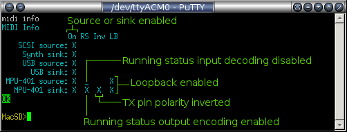
- mpu_401_source_rs=[true|false] - Enable running status decoding on the MPU-401 source. Disable this for SoundBlaster 16 and AWE32 cards affected by the hanging note bug.
- mpu_401_sink=[true|false] - Enable transmission of MIDI data to the MPU-401 interface on the expansion port.
- mpu_401_sink_rs=[true|false] - Enable running status encoding on the MPU-401 sink. Leaving this option enabled is recommended, however it may cause problems with non-standard MIDI hardware.
- mpu_401_sink_invert=[true|false] - Invert the polarity of the MPU-401 sink UART output. When set to false, the output pin idles at 3.3V with low pulses. When set to true, the output pin idles at 0V with high pulses. The true option allows the sink output pin, together with ground, to form a current source for driving an opto-isolated MIDI input on an external device. See the Expansion Port section for more information.
- mpu_401_loopback=[true|false] - If true, MIDI data received on the MPU-401 source pin will be forwarded to the MPU-401 sink/output pin. This feature can be used when connecting MacSD between a SoundBlaster card and an external synthesizer / tone generator to filter hanging notes. If false, only events received on other interfaces will be sent through the MPU-401 sink/output.
| MIDI Configuration Summary | ||||
| [midi] Configuration Section | Terminal Interface | Values | Default | |
| SCSI source enable | scsi_source = n | midi scsi_source n | true, false | false |
| Synthesizer sink enable | synth_sink = n | midi synth_sink n | true, false | false |
| USB source enable | usb_source = n | midi usb_source n | true, false | false |
| USB sink enable | usb_sink = n | midi usb_sink n | true, false | false |
| MPU-401 source enable | mpu_401_sink = n | midi mpu_401_sink n | true, false | false |
| MPU-401 source running status | mpu_401_source_rs = n | midi mpu_401_source_rs n | true, false | true |
| MPU-401 sink enable | mpu_401_sink = n | midi mpu_401_sink n | true, false | false |
| MPU-401 sink running status | mpu_401_sink_rs = n | midi mpu_401_sink_rs n | true, false | true |
| MPU-401 sink invert polarity | mpu_401_sink_invert = n | midi mpu_401_sink_invert n | true, false | false |
| MPU-401 loopback | mpu_401_loopback = n | midi mpu_401_loopback n | true, false | false |
Monitoring MIDI status
Modifying a MIDI parameter through the terminal interface or sending a midi info command results in a report of all MIDI parameters. Enabled options are represented by an X while disabled options show an underscore:
10. MIDI Synthesizer
MacSD features a sample-based MIDI synthesizer. Waveform data stored in a patch file on the SD card is loaded, transformed and mixed by the processor in real time according to streaming MIDI events. The audio output signal is generated on the CD audio out header. The synthesizer uses a different audio driver than the CD audio system, which precludes simultaneous CD audio and synthesizer playback. In cases where both features are engaged, CD audio takes precedence over the synthesizer.
Background
The MacSD synthesizer is an original design, partially written in optimized assembly. Melodic samples were sourced from the Korg X50, a descendant of the Triton synthesizer. Drum samples were sourced from the Korg X50, Yamaha MU100 and Roland SC-55.
MIDI Features
- General MIDI instruments and percussion
- 13 drum kits with optional lock (program change disable)
- Up to 32 voice polyphony (dependent on card performance)
- 32KHz stereo output with 13.75 bit resolution
- Three reverb settings
- Variable 3D depth effect
- Hanging note cancellation
- Replacement for QuickTime Musical Instruments on Macs, increasing game performance by freeing CPU cycles and memory while providing higher quality music.
- Hardware wavetable solution for classic PCs (SCSI optional), without memory-consuming TSRs.
- volume_master=[0-100] - This control uniformly scales the amplitude of all synthesizer audio output. If set too low, audio quality will be degraded through a loss of resolution. If set too high, excessive clipping will occur, which will also degrade audio quality. If set to an extremely high value, loud clicks and pops may be heard. This control is not mapped to the MIDI "volume" controller.
- volume_melodic=[0-100] - Scales the volume of all MIDI channels except for channel 10, independently of the "volume" MIDI controller.
- volume_drums=[0-100] - Scales the volume of MIDI channel 10, independently of the "volume" MIDI controller.
- depth=[0-100] - This parameter modulates the phase shift between the left and right audio channels based on the pan controller, enhancing spatial imaging. Higher values will increase perceived spatial separation between instruments.
- reverb=[0-2] - Simulates the effect of sound reflections in the listening environment. 0 minimizes reverb, 1 is a mild effect suitable for most music and 2 is the heaviest effect which can enhance some genres of music (like electronic/dance).
- drum_kit=n - The synthesizer includes thirteen General MIDI drum kits of varying musical styles. Drum kits may be selected through a MIDI program change message, through the macsd.ini configuration file, or through the USB interface. The drum kit lock feature may be enabled to prevent drum kit changes over MIDI. The following drum kit program numbers (1-128 range) are available:
Synthesizer Drum Kit Program Map Korg X50 (2007) Yamaha MU100 (1997) Roland SC-55 (1991) Standard Kit 1 2 3 Room Kit 9 11 Power Kit 17 18 Electronic Kit 25 27 Analog/TR-808 Kit 26 28 Jazz Kit 33 Brush Kit 41
Setting the channel 10 program number to a value not specified in the above table will set program 1 (Korg X50 Standard Kit). - drum_kit_lock = [true|false] - When set to true, MIDI program change events on channel 10 are ignored. This prevents a MIDI song or application from changing the drum kit.
- The system clock speed must be set to 57 MHz, due to increased processing and bandwidth requirements.
- The General MIDI patch file (macsd_synth_gm1.mps) must be present and unfragmented in the root directory of the SD card. Other optional patch files may become available in the future to expand capabilities and support other MIDI standards.
- channel = [x|y] - The PWM channel to configure on the OPTION header.
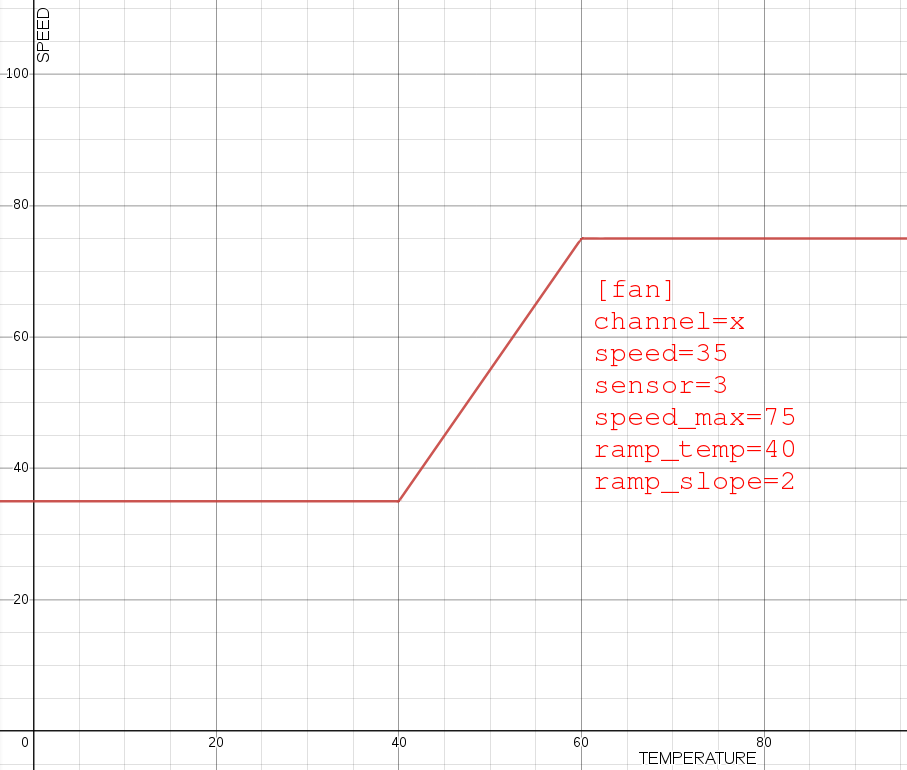
- speed = [0-100] - The minimum speed of the fan in percent.
- sensor = [0-7] - Which sensor channel to use to control fan speed. Defining this optional parameter puts the fan channel in variable speed mode. If not defined, the fan channel operates in fixed speed mode and the following options will have no effect.
- speed_max = [0-100] - The maximum speed of the fan in percent. The default value is 100. Affects variable speed mode only.
- ramp_temp = [20-90] - The temperature above which fan speed is increased above the minimum value. The default value is 40. Affects variable speed mode only.
- ramp_slope = [0-100] - Fan speed is increased n percent (linear) for each degree Celsius above ramp_temp, not exceeding speed_max percent. The default value is 5. Affects variable speed mode only
- fan speed [speed] [channel] - Set the speed of the specified fan channel. The [channel] argument is optional and will default to channel X if both channels are active. If a fan channel is in variable speed mode, setting the fan speed manually will set it to constant speed mode and dissociate it from any temperature sensor. The fan channel will return to variable speed mode when MacSD is reset.
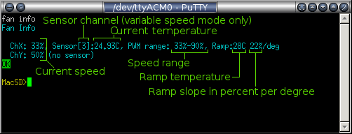
- fan info - Show the status of all enabled fan channels:
- channel=[0-7] - Specifies a sensor channel to enable. Sensor channels specified in [fan] sections are enabled automatically and do not require a [sensor] section.
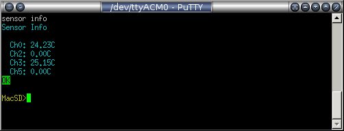
- sensor info - Show the current temperature readings for all enabled sensor channels:
- image_file=filename - Specifies the CD image file to be added to the disc catalog. The filename is case insensitive and may be enclosed in quotes. No directories are allowed; the file must be located in the root directory of the FAT32 volume. This attribute is required for [disc] sections.
- id=[1-100] - The ID for this image. This mandatory attribute is an integer from 1 to 100 and must be unique for each [disc] section.
- pcm_byte_order=[little|big] - This optional attribute is only applicable to audio and mixed-mode disc images (*.bin). It defines the byte order of CD audio data. Audio data is normally encoded as little endian, but some programs (cdrdao) rip audio as big endian. If unspecified, audio byte order is detected when the disc is mounted so this option is usually unnecessary.
- ISO - The ISO image format represents the first and only track of a data CD. It is not suitable for audio or mixed-mode discs. Data is encoded as 2048-byte sectors with no headers, error correction data or other metadata. This is the optimal format for data-only discs and yields a 15% file size and performance advantage over the BIN format. These images often have a .iso file extension, but .toast is also common.
- BIN - The BIN format is a raw image of a disc which may span multiple tracks. This format preserves all 2352 bytes per sector. For audio tracks, all 2352 bytes represent PCM data. For MODE1 data tracks, 2048 bytes are used for data with the remainder used for error correction and other purposes. Because they are not self-contained, there are unique requirements for using BIN images:
- BIN files must be accompanied by TOC or CUE files, which describe the layout of tracks in the BIN image.
- When specifying a BIN image in a [disc] or [n:cdrom] section, the name of the BIN file is required (rather than the TOC/CUE file).
- The TOC or CUE file must have the same base name as the BIN file, but with a .toc or .cue extension. For example, when MacSD loads the BIN image file alone_in_the_dark_2.bin, it will search for alone_in_the_dark_2.toc and alone_in_the_dark_2.cue in the root directory. If neither is found, an error condition will be set and the disc will be treated as having a single track.
- If a disc image's size in bytes is not a multiple of 2048 or if the filename ends with .bin/.BIN, it will be mounted as a BIN image.
- Multiple BIN files per disc (one per track) is not supported.
- disc queue [disc_id] [scsi_id] - Set the ID of the next disc that will be loaded when the specified CD-ROM drive is ejected. As a shorthand alias for this command, disc q is also accepted.
- disc eject [scsi_id] - Eject the CD-ROM drive at the specified SCSI ID. This causes the next disc in the catalog sequence to be loaded. As a shorthand alias for this command, disc e is also accepted. Using this command with Macintosh hosts is not recommended and will likely cause errors since the Macintosh prevents medium removal.
- disc load [disc_id] [scsi_id] - This is equivalent to executing a disc queue command, followed by a disc eject command. As a shorthand alias for this command, disc l is also accepted.
- PWR - The board is receiving power on the SCSI TRMPWR line. This LED is not under firmware control.
- SCSI - Indicates SCSI bus activity directed toward any device ID (emulated, physical or absent).
- SD - Indicates SD card activity
- FRAG - If a fragmented image file is loaded, this LED will remain on until power is lost. See the filesystem fragmentation section for more information.
- PCM - Indicates active PCM (CD audio) playback.
- ERR - This LED indicates one or more error conditions by rotating through a series of flash codes. See the error code section for more information.
- BL - Indicates the bootloader is active (BL jumper is set). When the bootloader is active, the meaning of other LED indicators may be different than described in this section.
- A - Illuminated when overclocking is enabled.
- B - This LED has no function in this firmware release, but may be used in future releases.
- Terminator LED - Located within the terminator DIP socket and illuminated while pull-up termination is active on the SCSI bus. If this LED is not on when the Mac is running, it may indicate the bus is missing termination.
- SD power LED - Located next to the SD card, this LED is tied directly to the SD card power supply and indicates the card is receiving power.
- Download the latest firmware image file from macsd.com to the root directory of a FAT32-formatted SDHC or SDSC card. The macsd.ini configuration file is not required to update firmware.
- Ensure only one firmware image file is present in the root directory of the card.
- With the Mac's power turned off, insert the SD card into the MacSD.
- Set the BL jumper.
- Turn the Mac on and observe the status LEDs:
- The SD LED will flash rapidly until the verification and installation process is complete (about 20 seconds).
- On success, the SCSI LED will pulse slowly.
- If the update fails, the error LED will indicate one or more error codes. See Bootloader Error LED Codes.
- Remove the BL jumper
- Cycle power to the Mac to run the newly installed firmware.
- Turn the Mac off
- Remove the BL jumper
- Turn the Mac on (partition type is changed within one second)
- Turn the Mac off (shut down safely if booting has begun)
- Install the BL jumper
- Turn the Mac on and allow the allow the update to complete
- 2 flashes: No macsd_x.x.x.fwi firmware update file found in the root directory
- 3 flashes: More than one macsd_x.x.x.fwi firmware update file found in the root directory
- 4 flashes: Unknown SD card format
- 6 flashes: Firmware update file is corrupt or has been renamed
- 7 flashes: Unable to initialize SD card
- 2 flashes: No memory card detected
- 3 flashes: No macsd.ini file found in the root directory
- 4 flashes: Error parsing TOC or CUE file
- 5 flashes: Malformatted track entry dropped from TOC or CUE file
- 6 flashes: No corresponding TOC or CUE file found for a BIN image - The link between BIN and TOC/CUE files is established on demand, not on startup; therefore this error is set for a given disc upon mounting.
- 7 flashes: Disc catalog mount failure
- 8 flashes: Excessive fragmentation - Set if mounted images span more than 127 total fragments.
- 9 flashes: SCSI request error
- 10 flashes: General configuration error - Set when a known configuration option is set to an illegal value. Unrecognized options will be ignored without causing an error.
- 11 flashes: FAT32 filesystem error / bad format
- 12 flashes: Error in macsd.ini file [disc] entry (missing/duplicate filename, missing/duplicate/out-of-range ID, invalid PCM byte order)
- 13 flashes: Partition error
- 14 flashes: Missing or damaged image file
- 15 flashes: Composite device error
- 16 flashes: Resource conflict (I/O pin assigned to multiple functions)
- 17 flashes: Synthesizer configuration or patch file error
- Forced perfect termination (FPT)
- Pull-up termination
- Pull-down termination
- Arrays are directional. Pin 1 is common, which is marked with a dot and must be aligned with either VCC or GND depending on termination mode.
- Pin 1 may be identified using a multimeter: Resistance between pins 1 and 2 equals the nominal resistance of the array. Resistance between pins 9 and 10 is double.
- Arrays must be installed as a pair for pull-up and pull-down termination.
- Two 330 Ohm arrays are included, but values as low as 220 Ohm may be used.
- MacSD resistor arrays have the same pin configuration as those used in Quantum hard drives (pin 1 is common).
- External LEDs (up to 8, any color)
- Temperature sensors (up to 8)
- MIDI/MPU-401 source/input
- MIDI/MPU-401 sink/output
- Use caution and reliable connections when attaching external LEDs.
- Shorting an LED line may result in permanent damage to the processor.
- LEDs connected with incorrect polarity can illuminate erratically and cause similar behavior in other LEDs.
- Do not connect reserved pins
[synth] configuration section attributes and terminal commands:
| Synthesizer Configuration Summary | ||||
| [synth] Configuration Section | Terminal Interface | Values | Default | |
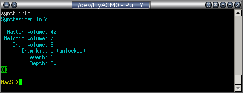
| Master volume | volume_master = n | synth vol n | 0-100 | 42 |
| Melodic volume | volume_melodic = n | synth vol melodic n | 0-100 | 72 |
| Drum volume | volume_drum = n | synth vol drum n | 0-100 | 80 |
| Depth | depth = n | synth depth n | 0-100 | 60 |
| Reverb | reverb = n | synth reverb n | 0-2 | 1 |
| Drum kit | drum_kit = n | synth drum_kit n | 1,2,3,9,11,17,18,25,26,27,28,33,41 | 1 |
| Drum kit lock | drum_kit_lock = n | synth drum_kit_lock n | true, false | false |
| View status | synth info | |||
Requirements
Card performance and the SD LED indicator
While the synthesizer is active, MacSD executes a high volume of random reads from the SD card. Some SD cards may stall when specific sectors are accessed, resulting in latencies of several hundred milliseconds. These stalls will cause breaks in the audio output. Normally during synthesizer playback, the SD LED remains lit (with a slight flicker) as MacSD fetches streams of data. If a stall condition is detected while the synthesizer is active, the SD LED will flash rapidly for approximately ten seconds. See the Card Requirements section for more information on resolving this condition.
Hanging notes
Missing or extraneous bytes in the MIDI data stream can result in hanging notes or other audible glitches. The synthesizer mitigates this issue by turning off any voices held longer than nine seconds. Some PC sound cards such as the Creative Labs SoundBlaster 16 and AWE32 series are known to generate hanging notes due to a bug. See the MIDI Interface and Router section for more information about these cards.
Monitoring synthesizer status
Modifying a synthesizer parameter through the terminal interface or sending a synth info command results in a report of all synthesizer parameters:
11. PWM Fan Controller
MacSD can control up to two PWM-enabled cooling fans. A fan may be configured to maintain a steady speed, or vary its speed according to the temperature reading of one of eight sensors. Fan speed may also be modified through the USB terminal interface. The PWM output is designed to Noctua's specification. Other fans accepting a 25KHz PWM signal will also work. Unconfigured fan channels run at 100% speed.
Constant speed mode
A fan channel is maintained at a constant speed if not associated with a temperature sensor, or if the fan speed is overridden by a terminal command. A constant speed fan requires only the channel and speed parameters to be defined.
Variable speed mode
When associated with a temperature sensor, a fan channel is under variable speed operation.
[fan] section attributes:
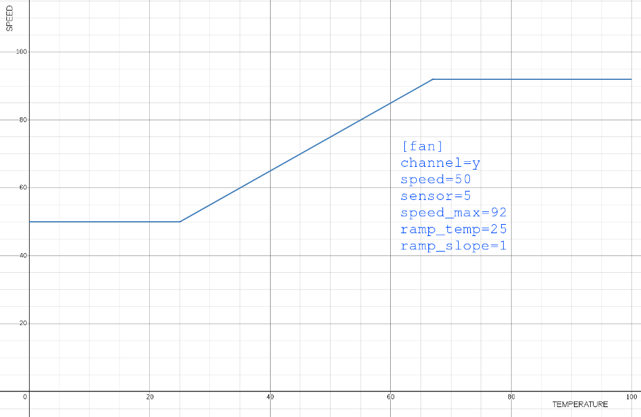
Variable speed configuration examples
PWM fan controller terminal commands:
12. Temperature Sensors
MacSD supports up to eight temperature sensors connected to the expansion port. These connections may be shared with external LEDs. The associated expansion port pins are multiplexed, allowing for both functions without conflicts. Detailed diagrams for connecting sensors are shown in the Expansion Port section of this manual.
Currently, the only method of monitoring sensors is the USB terminal interface. One ND03K00152K thermistor and one 3.3K resistor are required per channel. Variants of the ND03K00152K with tighter tolerance may be used. The value of the 3.3K resistor should be adjusted if trimming the temperature reading is required.
[sensor] Section Attributes:
Temperature sensor terminal commands:
13. Disc Catalog The disc catalog is an extension of CD-ROM emulation. A [disc] configuration entry associates a disc ID number with an image file on the SD card. When a disc image is ejected from an emulated CD-ROM drive, another is loaded based on the drive's configuration. The user may override the next disc to be loaded, or the range of discs to iterate through, using the terminal interface.
[disc] Section Attributes:
Disc catalog terminal commands:
The [scsi_id] parameter for the following commands is optional. Where omitted, it will default to that of the CD-ROM drive with the lowest SCSI ID. While the disc catalog itself must be configured through the macsd.ini file, discs may be loaded and queued through the terminal interface.
The MacSD board is equipped with a series of LEDs to indicate various conditions:
15. Firmware Updates and Bootloader Operation
Firmware updates are available from macsd.com as a file under 400KB, named in the pattern: macsd_1.2.3.fwi. To update the device firmware:
Bootloader v0.5.5 note for modern Mac users: FAT32 partitions formatted by MacOS are set to type 0x0B. While partition types 0x0B and 0x0C are valid for normal operation, the partition type for firmware updates must be 0x0C under bootloader v0.5.5. Bootloader v0.6.0+ can use either partition ID. The bottom of the MacSD PCB is labeled with the bootloader version.
To ease firmware updates for MacOS users, firmware as of v0.10.2 will convert type all 0x0B partitions to 0x0C at boot.
If a firmware update fails (2 error flashes) from a card newly formatted by MacOS:
16. Bootloader Error LED Codes
Applicable while the BL LED is illuminated
17. Application Error LED Codes
All error codes once set, persist until power is removed from the system or the SCSI initiator issues a reset. Multiple error codes can be set at once, in which case the ERR LED will rotate through each.
18. Termination Settings
Three termination configurations may be selected by installing or removing the two resistor arrays from the DIP socket:
Forced Perfect Termination (no resistors installed)
This mode is always active and absorbs signal reflections by clamping data line voltage to a range of approximately -0.5V to 3.7V. It does not affect the bus impedance or the load presented to devices. Begin with this option if you are unsure of which is appropriate.
Pull-up Termination (resistors to VCC)
This is selected by installing both resistor arrays with pin 1 inserted into the VCC column of the terminator DIP socket, leaving the GND column of the socket empty. Each data line is pulled up to 3.3V through its own resistor in the array. This option should not be used on an already functioning SCSI chain (where another device or the logic board is providing pull-up termination, indicated by an LED inside of the terminator DIP socket). Otherwise, there is a risk of excessive current flow through data lines which may result in damage to devices on the bus. Centris/Quadra/PowerMac-era machines often provide pull-up termination from the logic board, eliminating the need for this option. Pull-up termination on monochrome Macs is provided only by attached hard drives, so this option should be used if the MacSD is the only SCSI device present. The highest value (weakest) resistor array that yields good results should be used.
Pull-down Termination (resistors to GND)
This is selected by installing both resistor arrays with pin 1 inserted into the GND column of the terminator DIP socket, leaving the VCC column of the socket empty. With pull-down termination, each data line is biased toward ground through its own resistor in the array. This reduces the voltage level of both the 0 and 1 logic states for each data line. The output drivers on the MacSD may not be able to reliably drive a bus with very strong pull-up termination (<150 Ohms) as found in some Quantum hard drives. In this case, pull-down bias may resolve the issue without compromising the reflection-damping performance of the bus. The highest value (weakest) resistor array that yields good results should be used. As always, pull-up termination must be present somewhere on the bus.
Resistor Array Notes:
19. Expansion Port
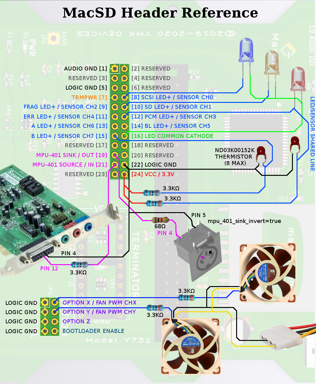
The expansion port/header allows connection of external devices. The header may be used to connect:
External LEDs
All eight indicator LED on the edge of the board, have anode (+) connections on the expansion header. External LED cathodes (-) must be connected to the common cathode pin on the expansion port, not ground. Current limiting resistors are not needed. Common cathode bicolor or RGB LEDs are useful for indicating multiple conditions where there is only room for a single LED. The intensity of external LEDs may be collectively adjusted using the ext_led_intensity configuration option.
Temperature sensors
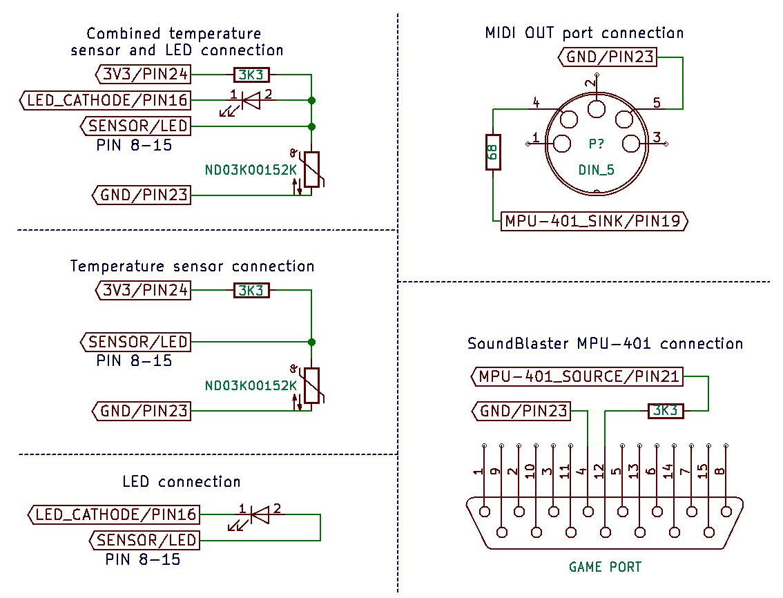
The same eight pins which drive external LEDs are used for temperature sensor inputs. All eight pins can interface with an external LED and a temperature sensor simultaneously. The sensor circuit is a voltage divider between ground and 3.3V. A 3.3K Ohm resistor is connected to 3.3V and forms the pull-up while an ND03K00152K thermistor connects to the resistor and ground, forming the pull-down. The node where the thermistor and resistor meet connects to a temperature sensor channel pin on the expansion port. There are no configuration options available for trimming the sensor. If trimming is needed, adjusting the pull-up resistor value is recommended.
MIDI/MPU-401 source/input
This input accepts MIDI data from SoundBlaster or compatible cards, through the game port or a wavetable header. Because these cards operate at 5 volts and MacSD operates at 3.3V, a 3.3K Ohm resistor is required between MacSD's input pin and the sound card for current limiting and level translation. The UART polarity is high/3.3V at idle. The data cable should also carry ground between MacSD and the SoundBlaster. The MIDI input is not opto-isolated. This is not an issue with SoundBlaster cards, however an isolator is recommended with other MIDI sources that don't share a ground with MacSD. A ground loop or device damage may result otherwise.
MIDI/MPU-401 sink/output
This output transmits data to an external MIDI device, such as a Yamaha tone generator or Roland Sound Canvas module. MIDI inputs on these devices are opto-isolated and accept a current source. The MIDI output pin, together with ground, forms a current loop which drives a MIDI input port. The output/sink polarity must be inverted so that the idle state is low and no current flows in the idle state. The polarity is inverted with the [midi] section option: mpu_401_sink_invert=true. A 68 Ohm resistor is required in series with the sink pin in order to limit current through it and the receiver's opto-isolator.
Expansion port pin table
⚠
| Expansion port pinout | ||||
| Pin | General | External LED | Temperature sensor | MPU-401 |
| 1 | Audio ground | |||
| 2 | Reserved | |||
| 3 | Reserved | |||
| 4 | Reserved | |||
| 5 | Logic ground | Sensor ground | Ground | |
| 6 | Reserved | |||
| 7 | TRMPWR | |||
| 8 | SCSI LED+ | Channel 0 | ||
| 9 | FRAG LED+ | Channel 2 | ||
| 10 | SD LED+ | Channel 1 | ||
| 11 | ERR LED+ | Channel 4 | ||
| 12 | PCM LED+ | Channel 3 | ||
| 13 | A LED+ | Channel 6 | ||
| 14 | BL LED+ | Channel 5 | ||
| 15 | B LED+ | Channel 7 | ||
| 16 | Common cathode | |||
| 17 | Reserved | |||
| 18 | Reserved | |||
| 19 | Sink / output | |||
| 20 | Reserved | |||
| 21 | Source / input | |||
| 22 | Logic ground | Sensor ground | Ground | |
| 23 | Reserved | |||
| 24 | 3.3V | |||
Expansion port connection schematics
20. Example Configuration File
macsd.ini:
; Example MacSD configuration file
; Any text on a line after a semicolon is ignored
[general]
system_clock_mhz=57 ; 57MHz clock speed required for synthesizer
pcm_tune=10024 ; Increase CD audio sample clock by 0.24%
ext_led_intensity=90 ; Set external LEDs to 90% intensity
int_led_intensity=75 ; Set internal LEDs to 75% intensity
[midi] ; MIDI routing options
scsi_source=true ; Accept MIDI over SCSI
synth_sink=true ; Enable the internal syntheesizer
usb_source=true ; Receive MIDI over USB
usb_sink=true ; Send MIDI over USB
mpu_401_source=true ; Receive MIDI over the expansion port UART
mpu_401_source_rs=false ; Disable running status decoding for incoming MPU-401 data mpu_401_sink=true ; Send MIDI over the expansion port UART
mpu_401_sink_rs=true ; Enable running status encoding for outgoing MPU-401 data
mpu_401_sink_invert=true ; Invert the UART TX polarity for driving a DIN MIDI port
mpu_401_loopback=true ; Route UART RX data to the TX pin
[synth] ; Requires synth_sink=true, system_clock_mhz=57 and patch file on card
volume_master=33
volume_drums=90
volume_melodic=70
depth=75 ; 3D depth effect
reverb=1 ; Moderate reverb
drum_kit=18 ; Yamaha MU100 power kit
drum_kit_lock=true ; Prevent drum kit changes over MIDI
[fan] ; Run fan channel X at a fixed speed of 45%
channel=x
speed=45
[fan] ; Fan channel Y responds to temperature channel 2 input
channel=y
speed=50 ; Set base/minimum speed to 50%
sensor=2 ; Use sensor channel 2 as input
speed_max=92 ; Run no faster than 92%
ramp_temp=25 ; Begin increasing speed at 25 degrees Celsius
ramp_slope=1 ; Increase speed by 1% per degree above 25C
[sensor] ; Enable sensor channel 4 for monitoring only
channel=4
[3:cdrom] ; Configure an AppleCD 300i Plus CD-ROM drive at SCSI ID 3
image_file=warcraft2.bin ; Begin with Warcraft II inserted
disc_id_min=20 ; Rotate through game discs
disc_id_max=29
[4:cdrom] ; Another CD-ROM drive at SCSI ID 4
disc_id_min=50 ; Rotate through audio CDs
disc_id_max=59
soft_eject_alert=true ; Play a beep when a disc is ejected
; Configure an emulated hard drive at SCSI ID 5. Macs
; will attempt to boot from higher SCSI IDs first.
[5:hdd]
image_file=system_7.1.img
; Configure a composite device at SCSI ID 2. The "floppies"
; directory contains disk images which are mounted
; simultaneously as a single hard drive.
[2:composite]
image_directory=floppies
convert_images=true ; Convert DiskCopy HFS images
; Configure an emulated hard drive at SCSI ID 1, mapped
; directly to MBR partition 2. Partitions may be >4GB.
[1:hdd]
partition=2
; Disc catalog:
[disc] ; Data-only disc
image_file=alone_in_the_dark.iso
id=20
[disc] ; Mixed mode data+audio disc
image_file=alone_in_the_dark_2.bin
id=21
[disc] ; Mixed mode data+audio disc
image_file=alone_in_the_dark_3.bin
id=22
[disc] ; Mixed mode data+audio disc
image_file=warcraft2.bin
id=23
[disc] ; Command & Conquer GDI Disc
image_file=cc_cd1.iso
id=24
[disc] ; Command & Conquer NOD Disc
image_file=cc_cd2.iso
id=25
[disc] ; Audio CD
image_file=RobZombie.bin
id=50
[disc] ; Audio CD
image_file=daft_punk.bin
id=51
[disc] ; Audio CD
image_file=eiffel65.bin
id=52